My invention relates to improvements in Electrical Power Accumulators, wherein the earth acting as rotor and the surrounding air as a stator, collects the energy thus generated by the earth rotating on its axis, utilises the same for power and other purposes.
In the development of my Wireless Train Control System for railways, covered by my United States Letters Patent Number 843,550, I discovered that, with an antennae consisting of one wire of suitable diameter supported by insulating means three to six inches above the ground and extending one half mile, more or less in length, the said antennae being grounded at one end through a spark gap and energised at the other end by a high frequency generator of 500 Watts input power and having a secondary frequency of 500,000 Hz, would produce in the antenna an oscillatory frequency the same as that of the earth currents and thus electrical power from the surrounding media was accumulated along the length of the transmission antenna and with a closed oscillatory loop antenna 18 feet in length run parallel with the transmission antenna at a distance of approximately 20 feet it was possible to obtain by tuning the loop antennae, sufficient power to light to full power, a series bank of fifty 60 watt carbon lamps.
Lowering or raising the frequency of 500,000 Hz resulted in diminishing the amount of power received on the 18 foot antenna. Similarly, raising the transmission antenna resulted in a proportionate decrease of power picked up on the receiving antenna and at 6 feet above the earth no power at all was obtainable without a change of potential and frequency.
It is the objective of my generic invention to utilise the power generated by the earth as described here, and illustrated in the drawings. The two figures in the drawings illustrate simple and preferred forms of this invention, but I wish it understood that no limitation is necessarily made as to the exact and precise circuits, shapes, positions, and structural details shown here, and that changes, alterations and modifications may be made when desired within the scope of my invention and as specifically pointed out in the claims.
DESCRIPTION OF DRAWINGS:

In Fig.1:
1 and 2 are alternating current feed wires supplying 110 volts 60 cycles to a high frequency generator.
3 is a switch with poles 4 and 5.
6 and 7 are connections of high frequency transformer 8 for stepping up the frequency to 500 KHz and the voltage to say 100 KV.9 is an inductance coil.
10 is a spark gap.
11 is a variable capacitor.
12 is the primary winding of transformer 8.
13 is the secondary winding of transformer 8 which is connected through wire 15 via variable capacitor 16 and wire 17 to ground 18.
14 is the wire from the other side of the secondary winding of transformer 8 connecting it to the main transmission antenna 19 which is supported by insulating means 20.
21 is spark gap from transmission antenna 19 to ground through wire 22, variable capacitor
23, and wire 24 to ground 24'.
Transmission antenna 19 may be of any desired length.
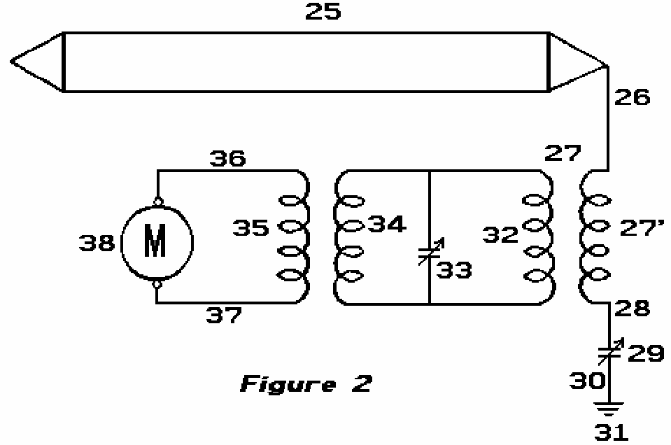
In Fig.2:
25 is a closed oscillating loop antenna of any desired length, which for greatest efficiency, is run parallel with transmission antenna 19 of Fig.1.
26 is the connecting lead between the antenna and step-down transformer 27 of which 27' is the secondary.
28 is the lead connecting the secondary winding 27’ to ground 31 via variable capacitor 29 and lead 30.
32 is the primary winding of transformer 27.
33 is a variable capacitor.
34 and 35 are frequency transformer windings, supplying current through leads 36 and 37 to motor 38, or any other power devices.
OPERATION OF THE INVENTION:
Close switch 3 to connect feed wires 1 and 2 to transformer leads 6 and 7.
Adjust spark-gap 10 and variable capacitor 11 so that a frequency of 500 KHz and 100 KV is delivered from secondary leads 14 and 15 of step-up transformer 8 of Fig.1.
Next adjust spark-gap 21 of transmission antenna 14 so that all nodes and peaks are eliminated in the transmission of the 100 KV and 500 KHz frequency along antenna 14.
The surges which occur, pass over gap 21 through lead 22 to variable capacitor 23 and then on to ground 24’
via lead 24.
The high frequency current of 500 KHz returns through the ground, to ground connection 18, up lead 17 to the variable capacitor 16 and via lead 15 to the secondary winding 13 of transformer 8 of Fig.1.
The alternating current produced by the 100 KV 500 KHz supply is the same frequency as the earth generated currents, and being in tune with them it picks up additional power from them.
Being the same frequency as the output from transformer 8 along wires 14, this produces a reservoir of high frequency current which can be drawn upon by a tuned circuit of the same 500 KHz frequency, as shown in Fig.2.
Antenna 25 is tuned to receive a frequency of 500 KHz which produces a current that passes to lead 26 through winding 27' of transformer 27, through wire 28, variable capacitor 29 and wire 30 to ground connection 31.
The high frequency currents of 500 KHz pass through to winding 32 and by variable capacitor 33 and windings 34 and 35 of the frequency transformer 27 are stepped down to a voltage and frequency suitable to operate motor 38 via leads 36 and 37. This makes available a current supply for any purpose whatsoever, such as the operation of aeroplanes, cars, railway trains, industrial plants, lighting, heating etc.
The return of current through the earth from transmission antenna 14 is preferable to a metallic return as a higher percentage of accumulation of earth currents is noticeable on receiving antennae of Fig.2 than from a metallic return, caused by the capacitance of the grounded circuit. I also prefer under certain conditions to use a single antenna receiving wire in place of the closed loop shown in Fig.2.
Under certain operation requirements I have found it expedient to have the transmission antenna elevated and carried on poles many feet above the earth and in that case a different voltage and frequency were found to be necessary to accumulate earth currents along the transmission antenna 14.
Revealed At Last...!
Free Energy Magnetic Generator and synthesizes many other technologies imbued with Nikola Tesla's technological identity

✔ Nikola Tesla’s method of magnifying electric power by neutralizing the magnetic counter-forces in an electric generator

Generates Energy-On-Demand: 👉 Free Energy Will Change Our World Forever
✔ Combination of induction motor and alternator
✔ Combine generators with induction motors - self-powered generators with rotary motion
✔ Various methods of generating high power immobile generators
✔ Or maybe called Overunity for the system. Mother Nature doesn't care about people calling or naming phenomena. Overunity/Free Energy, Zero Point Energy (ZPE) are just a few different words